Engineering guide
Impressed-Current Groundbeds: Deep-Well or Shallow, and Which Anodes
The groundbed is the anode side of an impressed current cathodic protection system: the anodes, their conductive backfill and the cables back to the power source. ISO 15589-1:2015 allows two types, deep-well and shallow. This guide sets out when each is considered, which anode materials and backfills are used, and the cable and venting details that decide how long a groundbed lasts.
Quick answer
What the groundbed design has to achieve
The groundbeds of an impressed current system shall be of the deep-well or shallow type, and their design and location shall meet three conditions (ISO 15589-1:2015, 9.3.1):
- the quantity of groundbed materials, anode and backfill, is compatible with the groundbed size and the design life of the system;
- the resistance to remote earth of each groundbed allows the maximum predicted current over its design life;
- harmful interference on neighbouring buried structures, including fences, foreign pipelines, facility piping and earthing systems, is avoided.
Location and type are chosen with the local conditions in view: electrolyte conditions and how resistivity varies with depth, groundwater levels, seasonal changes, terrain, shielding (especially for parallel pipelines) and the risk of third-party damage. The basic design includes a groundbed resistance calculation based on the most accurate resistivity data available. Where several groundbeds deliver the current, the output of each should be independently adjustable (9.3.1).
Deep or shallow
Choosing between a deep-well and a shallow groundbed
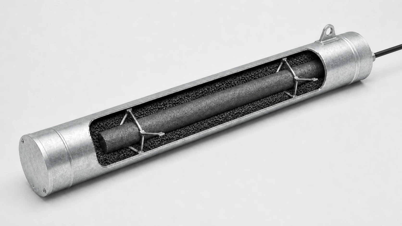
Schematic sketches, not to scale. Anode count, spacing, depth and cable routing come from the CP design.
| Consider a deep-well groundbed where | Consider a shallow groundbed where |
|---|---|
| hydrologic and geoelectric conditions underground allow it | electrolyte resistivity near the surface is far more suitable than at depth |
| electrolyte conditions at depth are far more suitable than at the surface | there is no risk of shielding by adjacent pipelines or other buried structures |
| there is a risk of shielding by adjacent pipelines or other buried structures | space is available for the groundbed |
| space for a shallow groundbed is limited | the current does not create unacceptable corrosion on adjacent buried structures |
| there is a risk of generating interference currents on adjacent installations |
Source: ISO 15589-1:2015, 9.3.2 and 9.3.3.
Construction details
What each type requires
Deep-well groundbeds
- Deep-well groundbeds should satisfy NACE SP0572. The detailed design includes the drilling procedure, resistivity of the electrolyte at various depths, how the borehole is completed and how the anodes and conductive backfill are installed. (ISO 15589-1:2015, 9.3.2)
- The borehole is designed and built so that water cannot transfer between geological formations and underlying strata are not polluted; some countries require special tests and documents for this. (9.3.2)
- Where necessary, a metallic casing stabilizes the borehole in the active section; it shall be electrically isolated from structures at the surface. A metallic casing is only temporary because the d.c. current consumes it; for permanent stabilization, non-metallic perforated casing should be used. (9.3.2)
- The groundbed resistance is calculated with the resistivity at the midpoint of the active length, considering layers of very different resistivity. (9.3.2)
- Adequate vent pipes should prevent gas blocking between the anodes and the conductive backfill. The vent pipe shall be made of a non-metallic, chlorine-resistant material. (9.3.2)
Shallow groundbeds
- Anodes are installed horizontally or vertically. In either case, the top of the conductive backfill is at least 0.8 m below ground level, or below the permafrost level where applicable. (9.3.3)
- The resistance calculation uses the resistivity at the centre-line of a horizontal groundbed or the mid-point of vertical anodes, again considering layered electrolytes. (9.3.3)
- The detailed design includes a construction procedure for the groundbed, the anodes and the backfill, and permanent marking should be considered for the beginning and end of each groundbed. (9.3.3)
Anodes and backfill
Impressed current anode materials
ISO 15589-1 lists high-silicon iron alloy (with chromium where the electrolyte has a high chloride content and regulations allow), magnetite, graphite, mixed-metal-oxide-coated titanium, conductive polymers and steel. Other materials may be used where reliable performance in the specific conditions is demonstrated and documented (ISO 15589-1:2015, 9.3.4).
The dimensions and mass of the selected anodes shall be capable of delivering 125 % of the required anode current output throughout the design life (9.3.4). Anode performance should be verified with the manufacturer.
| Anode material | Consumption rate, g/(A·y) | Typical anodic current density, A/m² |
|---|---|---|
| Scrap steel | 10,000 to 12,000 | 1 to 5 |
| High-silicon iron alloy | 250 to 1,000 | 10 to 30* |
| Impregnated graphite | 500 to 1,000 | 2.5 to 10* |
| Magnetite | 2 | 10 to 20* |
| MMO on titanium, in carbonaceous backfill | insignificant** | 50 to 100* |
| Conductive polymer, in carbonaceous backfill | insignificant** | 0.4* |
Source: ISO 15589-1:2015, Table 4, typical values in soil. *Observe the anode manufacturer's maximum current density. **These anodes are usually installed in carbonaceous backfill and their design life is generally governed by the backfill consumption rate. Carbonaceous backfill typically consumes 900 to 2,000 g/(A·y), with a typical anodic current density of 5 A/m².
Backfill
- Backfill is used to lower the anode-to-electrolyte resistance, unless the electrolyte already gives a satisfactory groundbed resistance, is homogeneous and uniform anode consumption is expected. (9.3.4)
- Electronically conductive backfills, such as coke, graphite and magnetite, are generally used with impressed current anodes because they reduce anode consumption and improve gas percolation. Electrolytic backfills such as bentonite and gypsum must be kept from drying out in operation. (9.3.4)
- The backfill should be checked for quantity, homogeneity and preparation against the project specification, and coke consumption is taken into account when the groundbed is sized. (9.3.4)
- Continuous conductive polymer anodes or titanium MMO wire should be considered, particularly for very high resistivity electrolytes around the pipeline. (9.3.4) See our conductive polymer and MMO flexible linear anodes.
Cables and venting
The cable is the weak point of a groundbed
- The minimum total cross section of the cable to the groundbed is 4 × 2.5 mm² or 10 mm², and 10 mm² for the cable to the protected pipeline. Conductors should be copper. (ISO 15589-1:2015, 8.5.1)
- Insulation shall suit both the environment, for example buried, immersed or chlorine-resistant, and the purpose of the cable, anodic or cathodic. The insulation of impressed current cables shall not be damaged where it is exposed to the electrolyte: a damaged anodic cable can make the protection ineffective in a very short time. (8.5.1)
- The integrity of the cable from the groundbed to the positive pole of the power source is essential; moisture ingress and oxidation of the conductor can lead to premature failure of the groundbed. Cable joints should be avoided as far as possible, and buried joints shall be suitable for permanent burial. (8.5.1, Note 2)
- Cable routes should be marked at approximately 100 m intervals and at every change of direction. (8.5.1)
- Terminating each anode lead separately in a junction box allows the output of each anode to be measured; for tank systems, NACE RP0193-2001 describes a test station or junction box that may include shunts for this purpose (NACE RP0193-2001, 9.3.3).
Cable sizes and insulation are covered in more detail in the cathodic protection cable guide.
Checklist
What to send for a groundbed quotation
- Groundbed type and layout — deep-well, shallow vertical or shallow horizontal, with the drawing or sketch, and the number of groundbeds.
- Design inputs — resistivity data (with depth for a deep well), required current and design life from the CP design.
- Anodes — material and form (HSCI tubular or canistered, MMO tubular or string, conductive polymer or MMO linear), size, quantity and the lead cable length for each anode.
- Backfill and hardware — backfill type and quantity, vent pipe material and length, casing (temporary metallic or permanent non-metallic perforated), centralizers and wellhead parts.
- Cables and terminations — header and lead cable size and insulation, splice kits, and the junction box with shunts if required.
- Documents — certificates and inspection records required for the anodes, cable and backfill, and the destination port.
Questions
Short answers
- When is a deep-well groundbed better than a shallow one?
- ISO 15589-1:2015 (9.3.2) says to consider a deep well where conditions at depth are far more suitable than at the surface, where adjacent pipelines or structures could shield the current, where space for a shallow groundbed is limited, or where there is a risk of interference currents on adjacent installations.
- How deep must a shallow groundbed be?
- Whether the anodes are horizontal or vertical, ISO 15589-1:2015 (9.3.3) requires the top of the conductive backfill to be at least 0.8 m below ground level, or below the permafrost level where applicable.
- Why does a deep-well groundbed need a vent pipe?
- Gas generated at the anodes can block the contact between the anodes and the conductive backfill. ISO 15589-1:2015 (9.3.2) calls for adequate vent pipes made of a non-metallic, chlorine-resistant material.
- How much margin is required on impressed current anodes?
- ISO 15589-1:2015 (9.3.4) requires the dimensions and mass of the selected anodes to be capable of delivering 125 % of the required anode current output throughout the design life of the system.
Sources
Standards used in this guide
- ISO 15589-1:2015 Petroleum, petrochemical and natural gas industries — Cathodic protection of pipeline systems — Part 1: On-land pipelines. Clauses 8.5.1 and 9.3.1 to 9.3.4; Table 4.
- NACE RP0193-2001 External Cathodic Protection of On-Grade Carbon Steel Storage Tank Bottoms (later revised as SP0193). Paragraph 9.3.3.
- Named but not quoted: NACE SP0572 for deep anode groundbeds and NACE TM0108 for testing catalysed titanium anodes, both referred to by ISO 15589-1.
Values are quoted from the editions listed. Where a project specification, purchase order or CP design states other values, those govern.
Factory supply & quotation
Complete ICCP Groundbed Anode & Cable Supply
CathPro supplies bare, cable-string and pre-canistered MMO tubular titanium anodes, MMO/Ti and conductive polymer linear anodes, high-silicon cast-iron (HSCI) anodes, PVDF/HMWPE and XLPE/PVC header cables, vent pipes and anodic junction boxes against your groundbed schedule.
Direct engineering desk (no web form required): sales@cathprocp.com · WhatsApp +86 159 7878 1890