Engineering guide
Cathodic Protection Test Stations: Locations, Types and Wiring
A test station is where the cables from the pipeline, its anodes, coupons and neighbouring structures come to the surface so the cathodic protection can be measured. This guide follows ISO 15589-1:2015 clause by clause: where stations are required, which conductors each type contains, the minimum cable sizes and how cables are attached to the pipe.
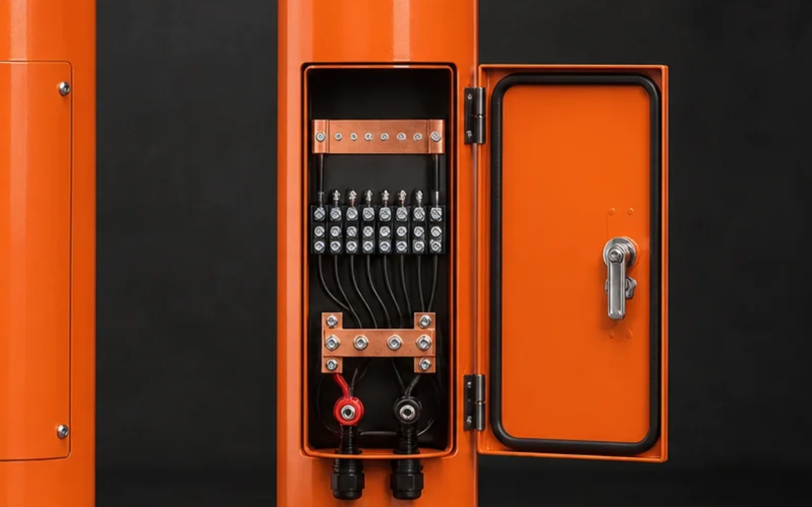
Quick answer
What a test station has to let you measure
ISO 15589-1 requires monitoring facilities along the pipeline route so that the performance of the cathodic protection can be measured (ISO 15589-1:2015, 11.1). At commissioning, the following measurements are made at test stations (12.3.4):
- ON-potential at the extremities of the protected pipeline and at critical locations;
- ON-potential and current on coupons, if any;
- potentials of neighbouring foreign structures, to check for any influence on them;
- ON-potential and current through the bond at bonded structures;
- ON-potentials that verify the electrical isolation of the pipeline at isolating joints, metal casings, reinforced concrete and earthing systems.
Each of these needs its own conductors, brought to a terminal that can be reached safely. That is why the station type follows its location on the route, and why the terminal schedule matters more than the enclosure style.
Where to install
Spacing and special locations
To monitor pipe-to-electrolyte potentials, currents and possible interference, test stations should be installed along the pipeline at intervals not greater than 3 km in rural areas and 1 km in urban or industrial areas (ISO 15589-1:2015, 11.2).
Required at special features
- isolating joints; connections to earthing systems; metallic casings;
- bond connections to other pipelines or facilities;
- connections with coupons and grounding;
- impressed current stations and drainage stations. (11.2)
Recommended where the pipeline
- crosses or runs parallel with a.c./d.c. traction systems, a.c. power lines or other pipelines;
- crosses major roads and embankments, railways and rivers;
- crosses highly aggressive soil, can be influenced by shielding, or runs close to other structures with cathodic protection;
- runs through non-metallic casings, or is used as a shunt for line current measurements. (11.2)
Stations are generally installed above the pipeline and identified. In urban and industrial areas, additional facilities can be needed so the reference electrode has soil contact at the measuring point (11.2 and Note). Line-current test stations are placed at regular distances, approximately every 10 km, and at cathodic protection stations, large river crossings and branch lines (Annex A, A.6).
Station types
Eight station functions and their conductors
ISO 15589-1 describes the contents of a test station by function rather than by catalogue name. A station may hold one or several cables to the pipeline; cables to permanent reference electrodes, coupons, probes, ER probes and d.c. decoupling devices; cables to neighbouring structures; cables to casings; and two or more pipe cables for line current measurements (ISO 15589-1:2015, 11.3). The sketches below show the usual conductor arrangement for each function. They are schematic, not to scale.
| Station function | Conductors | ISO 15589-1:2015 |
|---|---|---|
| Pipe-to-soil potential | Two separate pipe conductors, two connections; optional permanent reference electrode | 11.2, 11.3 |
| Line current | Two or more pipe conductors; four for a calibrated span (A, B, C, D) | 11.3, 11.8, Figure A.5 |
| Cased crossing | Pipe and casing conductors; at both casing ends to locate a contact | 11.6 |
| Isolating joint | A connection on each side of the joint, to one station | 11.7 |
| Bond to another pipeline | Two separate conductors on each pipeline | 11.5 |
| Coupon or probe | Coupon or probe cable with a disconnectable link; pipe cable; reference electrode where specified | 11.4, A.2.5 |
| Galvanic anode | Anode cable and pipe cable joined in an accessible station | 10.7 |
| Drain point | A test conductor separate from the current drain conductor | 11.9 |
At drain points, the separate test conductor is dedicated to the drain-point potential; a test station is not required where the drain point is on an above-ground section of the pipeline (11.9). In a galvanic anode circuit, permanent high-resistance measuring shunts should not be installed, because they reduce the anode current (10.7).
Cables and connections
Minimum cable sizes and how cables are attached
| Cable | Minimum total cross section |
|---|---|
| Potential measurement | 2 × 2.5 mm² or 6 mm² |
| Current span measurement | 4 × 2.5 mm² |
| Continuity bond | 4 × 2.5 mm² or 10 mm² |
| Galvanic anode system: cable to pipeline | 4 mm² |
| Galvanic anode system: cable to a single anode | 2.5 mm² |
| Impressed current system: cable to pipeline | 10 mm² |
| Impressed current system: cable to groundbed | 4 × 2.5 mm² or 10 mm² |
Source: ISO 15589-1:2015, 8.5.1. The conductor material should be copper. The project design can require larger sections for voltage drop, current, insulation, mechanical strength or temperature.
Separate connections are made between the pipeline and each core or cable with a separate function, so that cables used for potential measurement do not carry current and the reading is not distorted by voltage drop (8.5.1). All conductors in the same station are identified by colour coding or tags (11.2).
Attaching cables to the pipe
- Connections are made only by competent persons, in accordance with ISO 13847 or documented procedures approved by the pipeline operator. Typical methods include pin brazing, soft soldering, adhesive bonding (measurement cables only), fusion welding with metal deposit, stud welding, a welded steel piece with a pre-welded stud, and aluminothermic welding. (8.5.2)
- Cable connections are not welded on bends or within 200 mm of pipeline welds, fittings and valves. (8.5.2)
- For aluminothermic welding, copper penetration into the pipe is less than 1 mm, local hardness stays within the pipe specification, the charge should not exceed 15 g, and it should not be used on corrosion-resistant alloy pipelines. (8.5.2)
- Connections are checked mechanically (for example a sharp blow with a 1 kg hammer, see EN 12732) and electrically: the resistance of the connection, excluding the cable, should be below 0.1 Ω. The coating is then repaired so that water cannot enter. (8.5.2)
More on cable insulation and installation is in the cathodic protection cable guide.
Enclosure and safety
Enclosure, marking and hazardous areas
- Test facilities are terminated in a suitable test station or enclosure with easy access to the measuring terminals; all cables are permanently marked or colour coded to identify their purpose, and the facility has a permanent identification label. (ISO 15589-1:2015, 8.5.3)
- If there is any risk of high a.c. voltage on the pipeline, the measuring facility should be non-metallic (dead face) to avoid electric shock to the operator and the public. (8.5.3)
- Below-grade or surface boxes need mechanical strength for the expected traffic, for example on highways or inside above-ground installations. (8.5.3)
- Test facilities should be outside hazardous areas; a station inside a classified area conforms to that classification in accordance with IEC 60079-10-1 or an equivalent standard. (8.5.3)
- Where the route is remote or regular access is difficult, remote monitoring through cables, telemetry or other data transmission, together with permanent reference electrodes and coupons, should be used. (11.10) See monitoring-ready test stations.
Checklist
What to send for a test station quotation
- Station schedule — chainage or location of each station and its function: potential, line current, casing, isolating joint, bond, coupon, anode or drain point.
- Terminal schedule or schematic — number of circuits per station: pipe, reference electrode, coupon or probe, anode, casing, foreign line and spare terminals.
- Cables — conductor size, insulation, colour code or tag text and length for each circuit, checked against the minimum sections above.
- Enclosure — above-ground post, flush or below-grade box with its traffic loading, wall or pedestal box; material; dead-front panel where a.c. voltage is a risk; hazardous-area classification if any.
- Internal components — links, shunts and their ratings, bond resistors, diodes or surge protective devices, and any coupons or permanent reference electrodes supplied with the station.
- Quantity, labelling and destination — identification labels, packing per station, delivery port and schedule.
Questions
Short answers
- How far apart should cathodic protection test stations be?
- ISO 15589-1:2015 (11.2) recommends intervals not greater than 3 km in rural areas and 1 km in urban or industrial areas, plus stations at special features such as isolating joints, casings, bonds, impressed current stations and drainage stations, and at crossings with power lines, traction systems, railways, rivers and other pipelines.
- Why does a potential test station have two cables to the pipe?
- Two separate conductors on two different connections let the integrity of the connections be verified (ISO 15589-1:2015, 11.2). ISO also requires a separate connection for each function, so cables used for potential measurement do not carry current (8.5.1).
- What cable size is used for test station leads?
- ISO 15589-1:2015 (8.5.1) gives minimum total cross sections of 2 x 2.5 mm2 or 6 mm2 for potential measurement, 4 x 2.5 mm2 for current span measurement, and 4 x 2.5 mm2 or 10 mm2 for a continuity bond. The project design can require larger sizes.
- When should a test station be non-metallic?
- If there is any risk of high a.c. voltage on the pipeline, ISO 15589-1:2015 (8.5.3) says the measuring facility should be non-metallic (dead face) to avoid electric shock to the operator and members of the public.
Sources
Standards used in this guide
- ISO 15589-1:2015 Petroleum, petrochemical and natural gas industries — Cathodic protection of pipeline systems — Part 1: On-land pipelines. Clauses 8.5.1, 8.5.2, 8.5.3, 10.7, 10.8, 11.1 to 11.10 and 12.3.4; Annex A: A.2.5, A.6 and Figure A.5.
- Standards referred to by ISO 15589-1 and named here without quoting their content: ISO 13847, EN 12732, EN 15280 and IEC 60079-10-1.
Values are quoted from the edition listed. Where a project specification, purchase order or CP design states other values, those govern.
Factory supply & quotation
Drawing-Configured CP Test Stations, Coupons & Reference Cells
CathPro builds post-mounted and flush cathodic protection test stations in painted carbon steel, stainless steel, cast aluminum or UV-stabilized enclosures with project-configured brass/stainless terminal boards, shunts, bonding links, polarization coupons, permanent Cu/CuSO4 electrodes and CP cables.
Direct engineering desk (no web form required): sales@cathprocp.com · WhatsApp +86 159 7878 1890