Nominal area alone is not enough to select a joint or gland.
CP installation materials
CP Cables and Connection Systems
Cathodic protection cables and connection materials form the electrical path between anodes, structures, test points and power equipment. Reliability comes from matching conductor, insulation, joint system, termination and substrate as one field interface.
CathPro organizes project-specified cable, lugs, buried splice kits, heat-shrink components and exothermic connection materials into controlled, size-compatible item sets.
Technical pageStandards mapped by scopeData fields stated explicitly
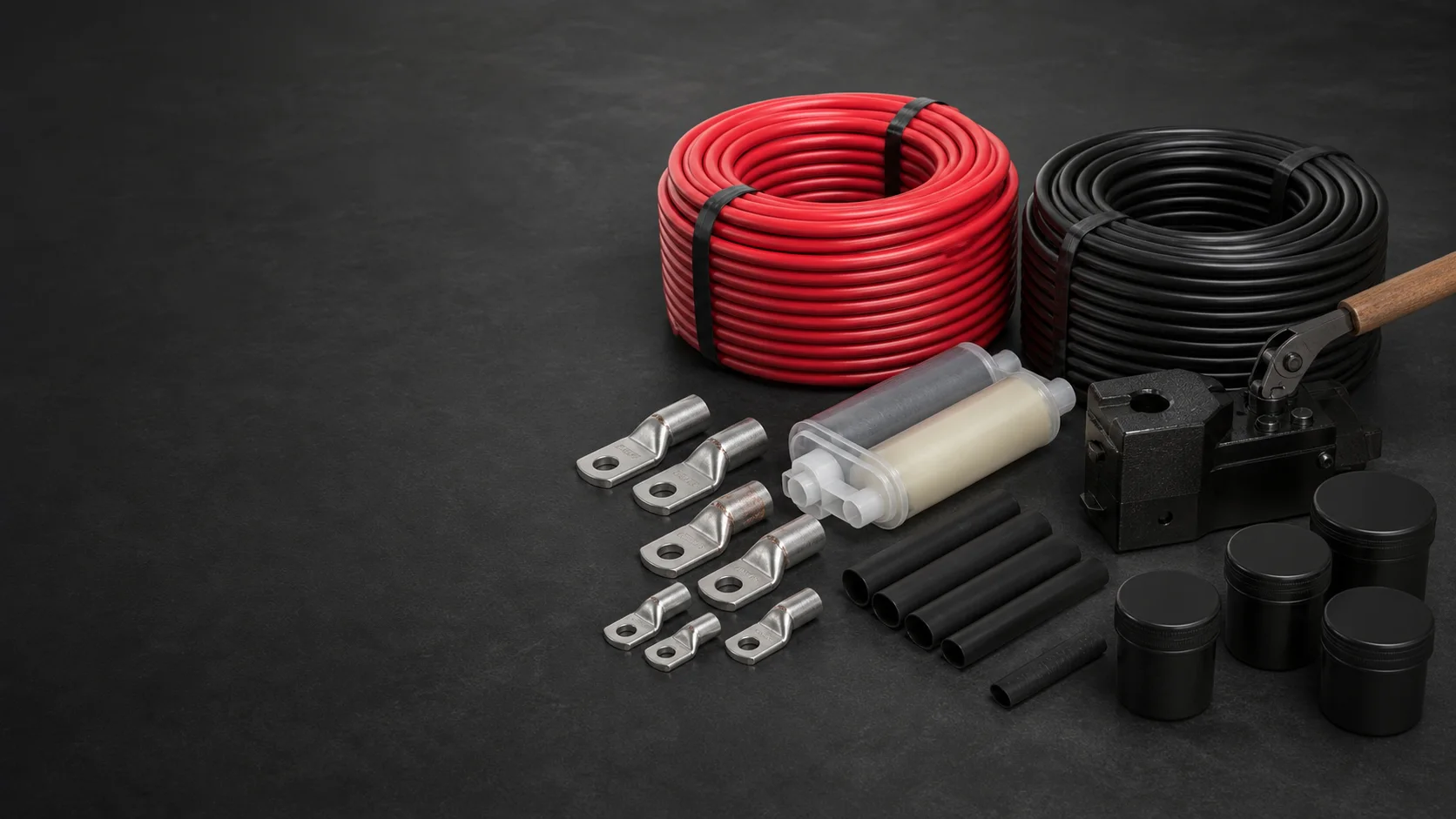
Every lug, splice and mold is matched to the actual interface.
Lengths, batch data and item codes stay visible through packing.
Product overview
The technical definition comes before the catalogue name.
A controlled product page separates the component's function, product construction and acceptance data from the wider cathodic protection design. This prevents a familiar name from hiding missing material, interface or inspection requirements.
- Primary function
- Carry CP current and measurement signals through durable, low-resistance field connections.
- Typical cable services
- Anode leads, structure cables, reference-electrode leads, test-station wiring and rectifier circuits.
- Connection families
- Crimped terminals, resin/heat-shrink splices and permanent exothermic attachments.
- Critical interfaces
- Conductor class, insulation OD, lug barrel/stud, splice geometry, substrate shape and environmental sealing.
Product construction
What the finished product contains
The same nominal conductor area can have different strand construction and insulation diameter. Connection materials are therefore selected from complete cable and substrate data, not from a generic product name.
Copper conductor
Solid, stranded or flexible conductor with nominal area, class, strand construction and maximum DC resistance defined by the cable specification.
Insulation or sheath
HMWPE, XLPE/PVC or other project-selected construction with material, wall thickness, outside diameter, color and voltage/service requirements.
Cable lug or terminal
Copper or tinned-copper barrel and palm matched to conductor size, strand class, stud diameter and approved crimping method.
Buried splice system
Mechanical/crimp connection, primary insulation, environmental seal and outer mechanical protection sized to both cable outside diameters.
Exothermic connection system
Mold, weld-metal charge, conductor geometry, steel/substrate geometry, ignition and handling accessories selected as one qualified method.
Identification and packing
Drum length, meter marking, project cable ID, kit contents, batch/lot references and area-based packing schedule.
Premium product studies
Products, configurations and critical interfaces
Premium studio product studies show representative CP cable, sealed joints, lugs, sleeves and connection accessories. Product compatibility is verified from conductor, insulation, substrate and approved connection-system data.
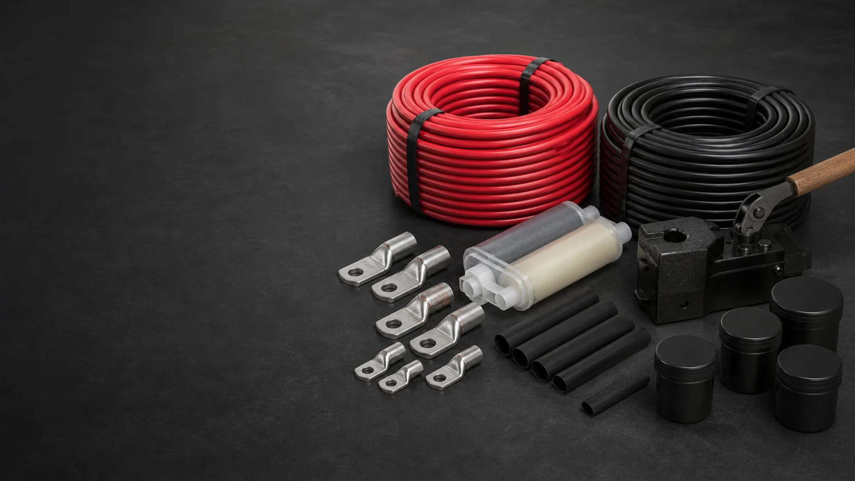
Cable and connection parts supplied as a compatible set
Conductor, insulation, lug, sleeve, joint and sealing components remain traceable to the released schedule.
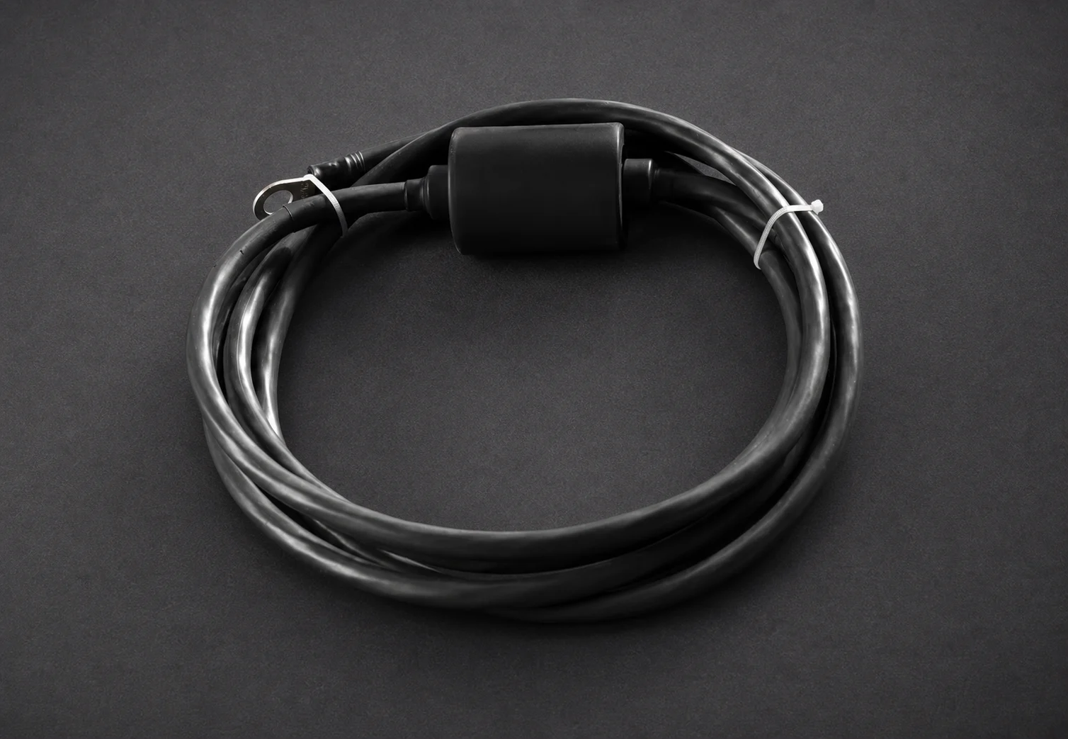
Factory lead and seal treated as one interface
Continuity, lead length, insulation condition and sealing construction are checked before release.
Selection begins with conductor and service environment
Insulation family, cable OD, termination, burial or immersion duty and structure-connection method are stated explicitly.
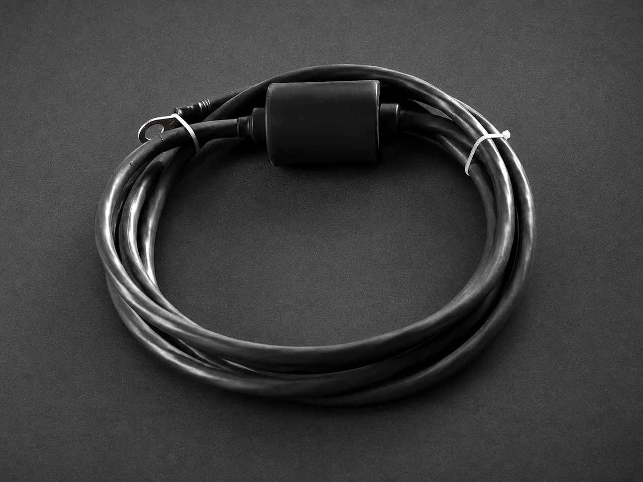
Mold, charge and accessories matched to the connection
Connection-system components are not mixed across unverified sizes or manufacturers; compatibility is released in the BOM.
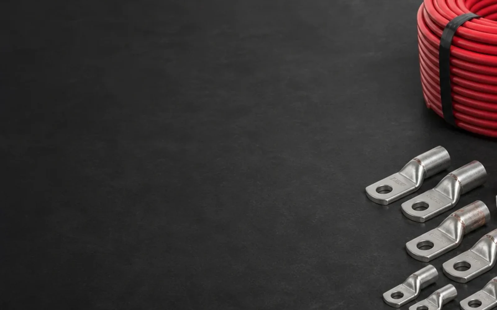
Lugs, conductor and insulation reviewed at interface scale
Conductor class, lug barrel, stud hole, crimping method and environmental sealing are defined as a compatible connection.
Product families
Configurations covered by this product range
Each configuration is released against its own datasheet, drawing or component schedule. Similar appearance does not make the technical definitions interchangeable.
Direct-burial CP cable
Project-specified copper conductor and robust insulation/sheath for anode and structure circuits.
Measurement and reference leads
Smaller signal conductors with color, shielding or termination requirements defined by the monitoring design.
Straight and branch splice kits
Sealed joint systems selected from conductor combination, cable OD, geometry and burial environment.
Exothermic attachment sets
Matched mold, weld metal and accessories for cable-to-pipe, cable-to-steel or approved grounding connection geometry.
Applicable standards
Standards mapped to the part they actually control
Listing a standard is not a certification claim. The purchase specification must identify the required edition, clauses, tests and evidence. Project documents take precedence where they add or modify requirements.
| Standard and role | Scope | How it applies to this product |
|---|---|---|
| IEC 60228:2023Conductor standard | Nominal cross-sectional areas, conductor construction and resistance requirements for conductors in insulated power cables and cords. | Conductor class, nominal area and resistance when IEC 60228 is invoked by the cable specification. Insulation and service requirements need a separate cable specification. |
| ISO 15589-1:2026CP system standard | Cathodic protection of on-land pipeline transportation systems, covering design, materials, equipment, installation and inspection. | The system designer's requirements for anodes, monitoring points, cabling, equipment and commissioning. It is not a standalone manufacturing certificate for every component. |
| NACE SP0169-2024Corrosion-control practice | Control of external corrosion on underground or submerged metallic piping systems. | CP criteria, design and installation context. Product configuration still follows the purchase specification and approved drawings. |
| IEEE 837-2024Connection qualification | Qualification of permanent connections used in substation grounding systems. | A relevant project reference for qualified permanent grounding connections, including applicable connection systems. It is not a blanket certification for all CP cable attachments. |
Edition review completed 22 July 2026. The edition named in the project requisition or purchase order remains the contractual basis.
Technical Data Sheet
Parameters buyers and engineers can verify
Numeric values are shown only where a current CathPro datasheet or recognized reference supports them. Custom assemblies use explicit project-defined fields instead of invented catalogue values.
Cathodic protection cable datasheet
Conductor and insulation data are shown together because they control electrical performance and physical compatibility.
| Data block | Parameters to state | Verification/document |
|---|---|---|
| Conductor | Material, nominal area, class, strand count/diameter and construction | Cable datasheet and conductor record |
| DC resistance | Maximum conductor resistance at 20 C and test length | IEC 60228 when specified and routine test record |
| Insulation/sheath | Material, nominal wall thickness, minimum thickness and outside diameter | Approved cable specification and dimensional record |
| Electrical/service rating | Rated voltage if applicable, temperature range and intended exposure/burial | Project cable standard |
| Identification | Color, surface marking, meter marking, project code and drum number | Marking schedule and final inspection |
| Supply length | Total quantity, drum/cut length, tolerance and drum data | Length record and packing list |
IEC 60228 controls conductors when invoked; it does not by itself define CP cable insulation, burial suitability or complete cable construction.
Splice and termination compatibility matrix
Every selected kit should be traceable to the actual cable and connection geometry.
| Interface | Compatibility fields | Required result |
|---|---|---|
| Cable lug | Conductor area/class, barrel ID, palm hole, stud and plating | Approved lug and crimp-die reference |
| Straight splice | Cable A/B conductor, cable OD, connector and joint length | Kit size and controlled installation sequence |
| Branch splice | Main/branch sizes, branch angle, connector and enclosure volume | Complete branch kit with sealing system |
| Heat-shrink seal | Recovered diameter, wall, adhesive and overlap | Fit over connector and both cable jackets |
| Resin joint | Resin type/volume, mold size, cable OD range and cure conditions | Sufficient fill and environmental seal |
| Gland/entry | Cable OD, thread, material and environmental rating | Compatible gland and enclosure entry |
Exothermic connection datasheet
The connection is selected from both conductor and substrate. Mold or charge numbers are not interchangeable without method verification.
| Selection field | Information controlled | Why it matters |
|---|---|---|
| Conductor | Material, nominal size, strand form and coating | Defines conductor cavity and weld volume |
| Substrate | Pipe/plate/rebar material, wall/section and surface geometry | Defines mold face and heat input constraints |
| Connection orientation | Cable-to-pipe, cable-to-plate, cross/run or project detail | Defines mold geometry |
| Weld material | Manufacturer/system, charge size and batch | Must match the approved mold and procedure |
| Accessories | Handle clamp, igniter, disk, packing material and surface tools | Ensures the complete field method is available |
| Qualification | Project procedure, installer training and any required connection qualification | Controls safe and repeatable application |
Manufacturing control
From approved data to an inspectable product
The process is organized around released drawings, material identity, controlled interfaces and inspection records. No unapproved change is treated as equivalent by default.
Cable schedule review
Map every circuit to conductor, insulation, color, length, drum and marking requirements.
Interface matching
Check lugs, glands, splice kits and exothermic components against conductor and cable outside dimensions.
Incoming verification
Confirm product codes, dimensions, manufacturer data, batch information and visible condition against the approved schedule.
Kitting
Assemble complete joint or installation sets so required connectors, seals and consumables remain together.
Length and identification control
Record drums or cut lengths and apply project IDs without covering manufacturer traceability.
Compatibility release
Use a second check to confirm each kit line matches the cable/substrate line before packing.
Area-based packing
Separate and label material by installation area, connection type or MTO item where the project schedule requires it.
Inspection and test plan
Checks tied to a stated acceptance basis
Inspection is useful only when the method, acceptance document and product identity are recorded together.
| Inspection item | Method or record | Acceptance basis |
|---|---|---|
| Cable data | Conductor, insulation, outside diameter, color, marking and length | Approved cable datasheet/schedule |
| Conductor resistance | Routine or type-test record when included | IEC 60228/project cable standard |
| Termination compatibility | Lug barrel/palm and gland range against conductor/cable OD | Compatibility schedule |
| Splice-kit completeness | Connector, insulation, sealing and mechanical-protection parts | Released kit BOM |
| Exothermic system | Mold, charge, conductor and substrate references | Approved connection method |
Application range
Where this product family is used
- Anode lead cables
- Structure connection cables
- Reference-electrode leads
- Test-station circuits
- Transformer-rectifier circuits
- Buried cable joints
- Pipeline attachments
- Groundbed installations
Engineering selection notes
Points that should remain visible in technical review
- Provide cable outside diameter as well as conductor size; splice kits and glands are selected on both.
- Do not combine molds, weld-metal charges and accessories from unverified systems or sizes.
- Exothermic welding should follow the approved connection method, substrate limitations and site safety procedure, performed by trained personnel.
Documentation
Evidence that follows the manufactured item
The final document set is defined by the order and ITP. Availability depends on the product, inspection scope and approved vendor-data requirements.
Cable datasheet
Conductor, resistance, insulation, OD, rating, color, marking and packing.
Cable and drum schedule
Circuit ID, cable type, total/cut length, drum number and destination area.
Compatibility schedule
Cable-to-lug, cable-to-gland, splice-kit and exothermic connection mapping.
Component datasheets
Manufacturer data and instructions for lugs, joints, glands and connection systems.
Packing list
Kit contents, batch/lot references and installation-area identification.
Technical questions
Common specification points
Answers focus on product definition and evidence, not on sales instructions.
Why is conductor size not enough to select a splice kit?
The connector must fit the conductor, while the sealing body must fit the insulation outside diameter and joint geometry. Both cable construction and burial condition are required.
What does IEC 60228 cover?
It defines nominal conductor areas, construction and resistance requirements for conductors in insulated cables. A separate cable specification defines insulation, sheath and service conditions.
What data selects an exothermic mold?
Conductor material/size, strand form, substrate material and geometry, connection orientation and the approved connection system all affect mold and charge selection.
How are installation kits checked before shipment?
Each kit is verified against a released compatibility schedule and BOM, then identified by circuit, connection type, area or MTO item as required.