Engineering guide
Cathodic Protection Cables: Minimum Sizes, Insulation and Connections
A cathodic protection system is only as reliable as the cables that carry its current and measurements for decades underground. ISO 15589-1:2015 sets a minimum cross section for each cable duty and rules for insulation, routing and connection to the pipe. This guide collects those requirements with the clause for each, and lists what to state when ordering cable and connection materials.
Quick answer
Five requirements every CP cable has to meet
- Fit for buried service, without metal armouring. Cables to pipelines, impressed current anodes, galvanic anodes, drainage stations and test stations shall be fit for buried service and should not have metal armouring, which can damage the insulation if the cable is bent excessively. (ISO 15589-1:2015, 8.5.1 and Note)
- Insulation chosen for the environment and the duty. The insulation shall suit the environment, for example buried, immersed or chlorine-resistant, and the purpose of the cable, anodic or cathodic. (8.5.1)
- Copper conductors. The conductor material should be copper. (8.5.1)
- Intact insulation on impressed current cables. The insulation of impressed current and drainage cables shall not be damaged where exposed to the electrolyte; a damaged anodic cable can make the protection ineffective in a very short time. (8.5.1 and Note)
- One function per cable. Cables installed as protective earth conductors are used only for that purpose, and each core or cable with a separate function gets its own connection to the pipeline. (8.5.1)
Minimum sizes
Minimum cross section by cable duty
ISO 15589-1 states the minimum total cross section; the design can call for more.
| System | Cable duty | Minimum total cross section |
|---|---|---|
| Impressed current | Cable to the protected pipeline | 10 mm² |
| Impressed current | Cable to the groundbed | 4 × 2.5 mm² or 10 mm² |
| Galvanic anodes | Cable to the protected pipeline | 4 mm² |
| Galvanic anodes | Cable to a single anode | 2.5 mm² |
| Other | Potential measurement | 2 × 2.5 mm² or 6 mm² |
| Other | Current span measurement | 4 × 2.5 mm² |
| Other | Continuity bond | 4 × 2.5 mm² or 10 mm² |
Source: ISO 15589-1:2015, 8.5.1. For tank-bottom galvanic anodes, NACE RP0193-2001 asks for lead wire at least 2 mm in diameter (#12 AWG), supplied attached by the anode supplier (7.3.7, 7.3.7.1).
Above these minimums, the cross section is designed on the basis of the voltage drop the design allows, the steady-state current, the insulation properties, mechanical strength, flexibility, operating temperature and economics (ISO 15589-1:2015, 8.5.1). Long anode leads in a deep-well groundbed and long header cables are where voltage drop usually decides the size.
Insulation
Matching the insulation to the duty
- Anodic cables. The cable from the groundbed to the positive pole of the power source carries current into the electrolyte at any defect. ISO 15589-1 calls its insulation integrity essential: moisture ingress and oxidation of the conductor can lead to premature failure of the groundbed. (8.5.1, Note 2) Where anodes can generate chlorine, the insulation has to be chlorine-resistant (8.5.1).
- Cathodic, measurement and bond cables. These still need insulation fit for buried service and an identification that lasts. (8.5.1, 8.5.3)
- Tank farms and oily ground. For tank-bottom systems, cable insulation should be selected for the expected conditions and be resistant to oil and water. (NACE RP0193-2001, 6.2.1, 7.3.7.1)
- Constructions. Single-insulated HMWPE cable is common for direct burial. For anode leads exposed to chlorine, dual-insulated constructions with a fluoropolymer inner layer under an HMWPE jacket are often specified. The project cable specification sets the construction, wall thickness and voltage rating.
- Identification. All cables are clearly marked or colour coded so that their purpose is unambiguous, and conductors in the same test station are identified by colour or tags. (ISO 15589-1:2015, 8.5.3, 11.2)
Installation
Laying and protecting the cable
- Cables are laid without coils or kinks and installed with care to avoid damaging the insulation. (ISO 15589-1:2015, 8.5.1)
- Cables should not be laid near power cables. (8.5.1)
- Protective sleeves, sufficient cover with warning tape, or burial in fine-graded soil or sand can be used, following local electrical and safety regulations. (8.5.1, Note 1)
- Cable routes should be marked at approximately 100 m intervals and at every change of direction. (8.5.1)
- Cable joints should be avoided as far as possible; buried or immersed joints shall be suitable for permanent burial or immersion. (8.5.1)
- Around tanks, NACE RP0193-2001 asks for slack in anode lead wires against settlement, and lead wires protected by at least 46 cm (18 in) of cover and/or conduit, with warning tape over direct-buried cable. (NACE RP0193-2001, 9.3.2, 9.5.7)
Connections
Connecting cables to the pipe and to anodes
- Cable connections to pipelines are made only by competent persons, in accordance with ISO 13847 or documented procedures approved by the pipeline operator. (ISO 15589-1:2015, 8.5.2)
- Typical methods are pin brazing, soft soldering, adhesive bonding (measurement cables only), fusion welding with metal deposit, stud welding, a welded steel piece with a pre-welded stud, and aluminothermic welding. (8.5.2, Note)
- Connections are not welded on bends or within 200 mm of pipeline welds, fittings and valves. (8.5.2)
- Aluminothermic welds keep copper penetration into the pipe below 1 mm and local hardness within the pipe specification; charges should not exceed 15 g, and the method should not be used on corrosion-resistant alloy pipelines. Welding on live pipelines follows a documented safety procedure. (8.5.2)
- Connections are verified mechanically, for example with a sharp blow from a 1 kg hammer (see EN 12732), and electrically: the connection resistance, excluding the cable, should be below 0.1 Ω. The coating is then repaired so that water cannot enter. (8.5.2)
- Galvanic anode cables are connected to the pipeline in an accessible facility, so potential and current can be measured; permanent high-resistance measuring shunts should not be installed in the anode circuit. (10.7)
Station layouts and the conductors each one needs are in the test station guide.
Checklist
What to send for a cable and connection quotation
- Cable schedule — each circuit with its duty (anodic, cathodic, measurement, bond), from and to, and cut or drum length.
- Conductor — cross section and strand class, checked against the minimum sections above and the design voltage drop.
- Insulation — construction (for example HMWPE, or dual insulation for chlorine exposure), wall thickness, voltage rating and colour or marking text.
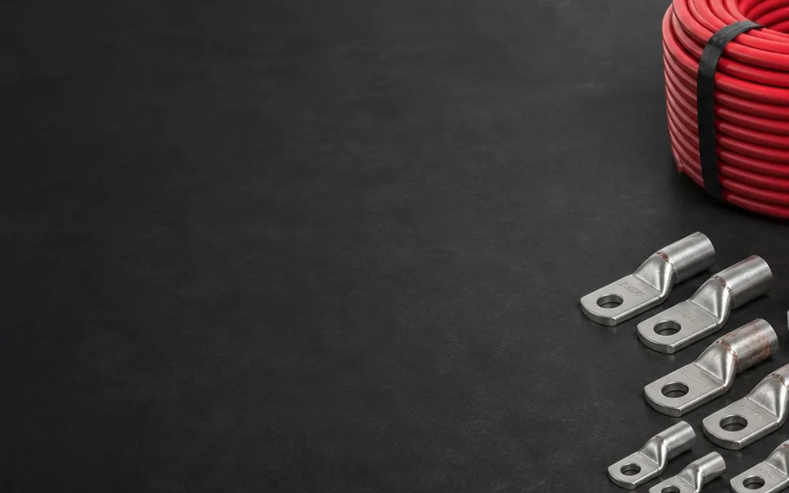
- Splices and terminations — straight or branch splice kits matched to the cable outside diameter, and lugs matched to conductor size and stud diameter.
- Pipe connections — connection method; for aluminothermic welding, the molds and charges matched to pipe diameter and cable size, with charges not above 15 g.
- Documents and packing — cable test reports, drum or coil labelling, packing per area and destination port.
Questions
Short answers
- What is the minimum cable size between a galvanic anode and the pipe?
- ISO 15589-1:2015 (8.5.1) gives a minimum total cross section of 2.5 mm2 for the cable to a single anode and 4 mm2 for the cable to the protected pipeline in a galvanic anode system. The design can require larger sizes.
- Can armoured cable be used for cathodic protection?
- ISO 15589-1:2015 (8.5.1) says CP cables should not have metal armouring, because the armouring can damage the insulation if the cable is bent excessively.
- Why must anode cable insulation be perfect in an impressed current system?
- A defect lets the anodic cable discharge current and corrode. ISO 15589-1:2015 (8.5.1) notes that a damaged anodic cable can make the protection ineffective in a very short time, and that moisture ingress and conductor oxidation can cause premature failure of the groundbed.
- How are CP cables attached to the pipe?
- By competent persons following ISO 13847 or approved procedures, not on bends or within 200 mm of welds, fittings and valves. Aluminothermic charges should not exceed 15 g, and the connection resistance excluding the cable should be below 0.1 ohm (ISO 15589-1:2015, 8.5.2).
Sources
Standards used in this guide
- ISO 15589-1:2015 Petroleum, petrochemical and natural gas industries — Cathodic protection of pipeline systems — Part 1: On-land pipelines. Clauses 8.5.1, 8.5.2, 8.5.3, 10.7 and 11.2.
- NACE RP0193-2001 External Cathodic Protection of On-Grade Carbon Steel Storage Tank Bottoms (later revised as SP0193). Paragraphs 6.2.1, 7.3.7, 7.3.7.1, 9.3.2 and 9.5.7.
- Named but not quoted: ISO 13847 and EN 12732, referred to by ISO 15589-1.
Values are quoted from the editions listed. Where a project specification, purchase order or CP design states other values, those govern.
Factory supply & quotation
Cathodic Protection Cables, Splice Kits & Pin/Thermite Connections
CathPro supplies single-core copper CP cables for structure return, header, anode lead, potential monitoring and bonding circuits in XLPE/PVC, HMWPE and chlorine-resistant PVDF/HMWPE insulations, coordinated with resin splice kits, exothermic weld charges/moulds and junction boxes.
Direct engineering desk (no web form required): sales@cathprocp.com · WhatsApp +86 159 7878 1890