Mechanical and electrical layouts are controlled together.
Monitoring hardware
Cathodic Protection Test Stations
A cathodic protection test station provides controlled, accessible measurement and connection points for structure, reference electrode, coupon, anode, bond and monitoring circuits.
The station is built from two coordinated documents: a general arrangement that defines the enclosure and installation, and a terminal schedule or schematic that defines every electrical function inside it.
Send the drawing, terminal schedule or specification directly. No form required. Email: sales@cathprocp.com
Supply identity: Project-sourced components; configured and assembled by CathProStandards mapped by scopeData fields stated explicitly
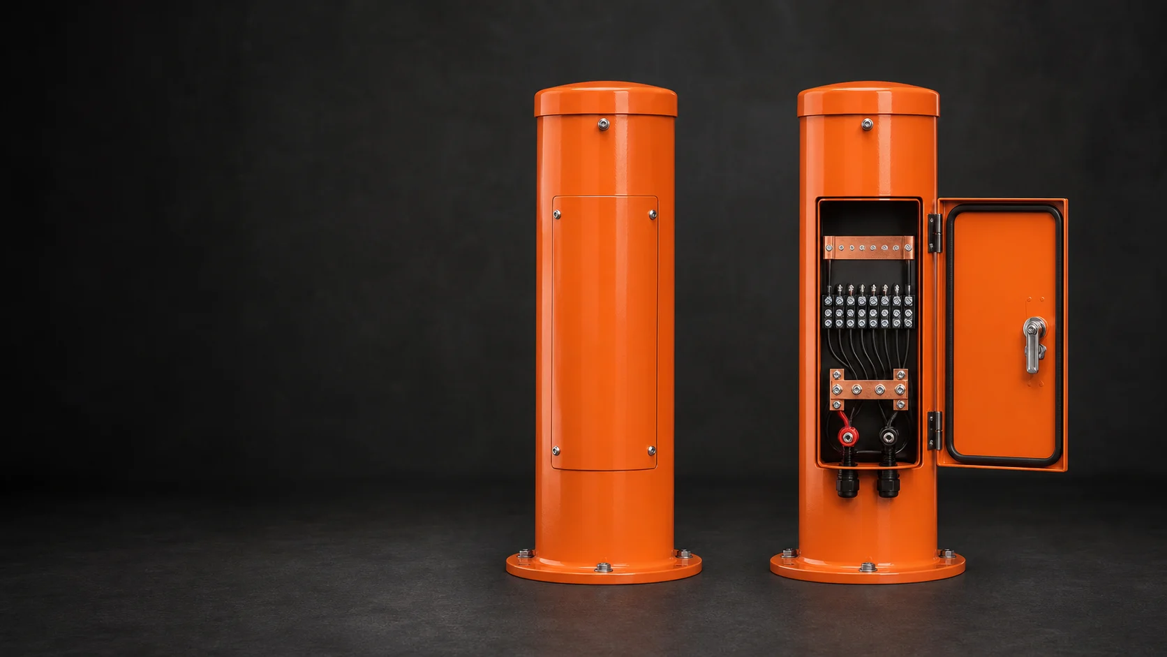
Material and rating follow the installation environment.
Components, labels and continuity are checked before release.
Product overview
The technical definition comes before the catalogue name.
A controlled product page separates the component's function, product construction and acceptance data from the wider cathodic protection design. This prevents a familiar name from hiding missing material, interface or inspection requirements.
- Primary function
- Provide repeatable field access for potential, current, continuity, bond and coupon measurements.
- Typical circuits
- Pipe, casing, reference electrode, coupon, galvanic anode, bond, shunt, spare and monitoring channels.
- Critical interfaces
- Terminal identification, cable glands, link/shunt ratings, enclosure protection, mounting and project tags.
- Configuration control
- No terminal is treated as generic; every position maps to a field cable and schematic function.
Product construction
What the finished product contains
A professional test station makes the field circuit understandable at first inspection. Physical access, terminal spacing and labeling are designed around actual cable sizes and measurement tasks.
Post or enclosure
Powder-coated steel, stainless steel, GRP, PVC or project-selected construction with mounting, access and finish defined on the GA.
Terminal board
Insulating support with terminal spacing, touch clearance and usable tool access matched to conductor and hardware size.
Terminals and links
Color-coded or tagged terminals, removable links, shunts, resistors or surge components arranged to the schematic.
Cable entry system
Glands, conduits, grommets, sealing and strain relief coordinated with cable quantity and outside diameter.
Identification
External station tag, internal terminal designations, warning labels and durable circuit schedule.
Monitoring provision
Reserved space, DIN rail, antenna/power interfaces or mounting plate only when defined by the monitoring design.
Premium product studies
Products, configurations and critical interfaces
Premium studio views explain post, enclosure and terminal arrangements without being presented as a project FAT record. The approved GA, schematic, terminal schedule and actual release report remain the controlling evidence.
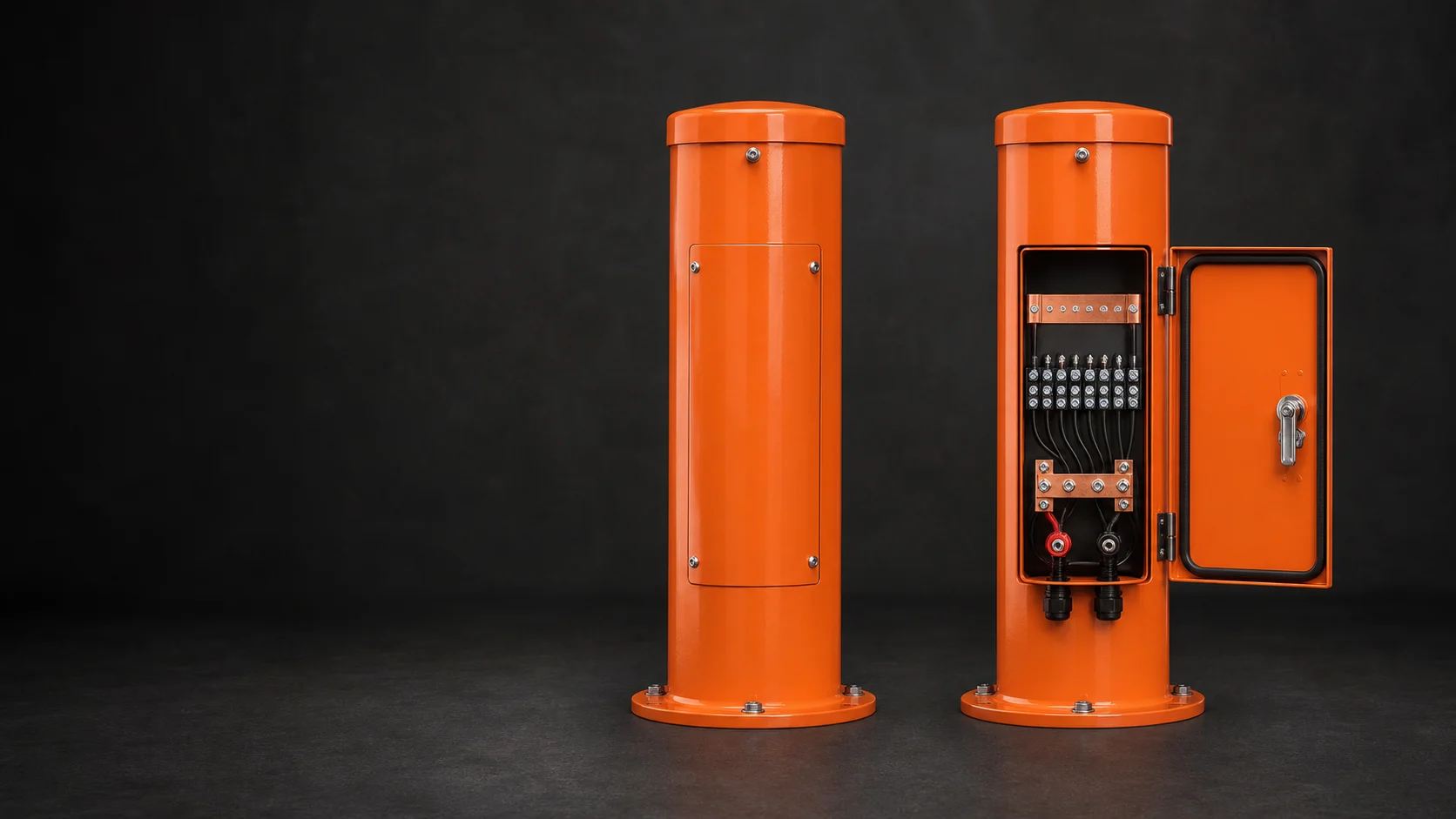
External access and internal functions designed together
Enclosure form, terminal count, labels, links and cable entries are coordinated from the released drawing set.

Compact monitoring points for route and plant locations
Post height, access, mounting, color and internal schedule are selected for the installation environment.
Usable working space around every terminal
Cable bend radius, tool access, link removal and durable identification are reviewed before enclosure size is fixed.

Station appearance follows its electrical function
The visual configuration supports technical review but does not replace component, continuity or environmental-rating evidence.
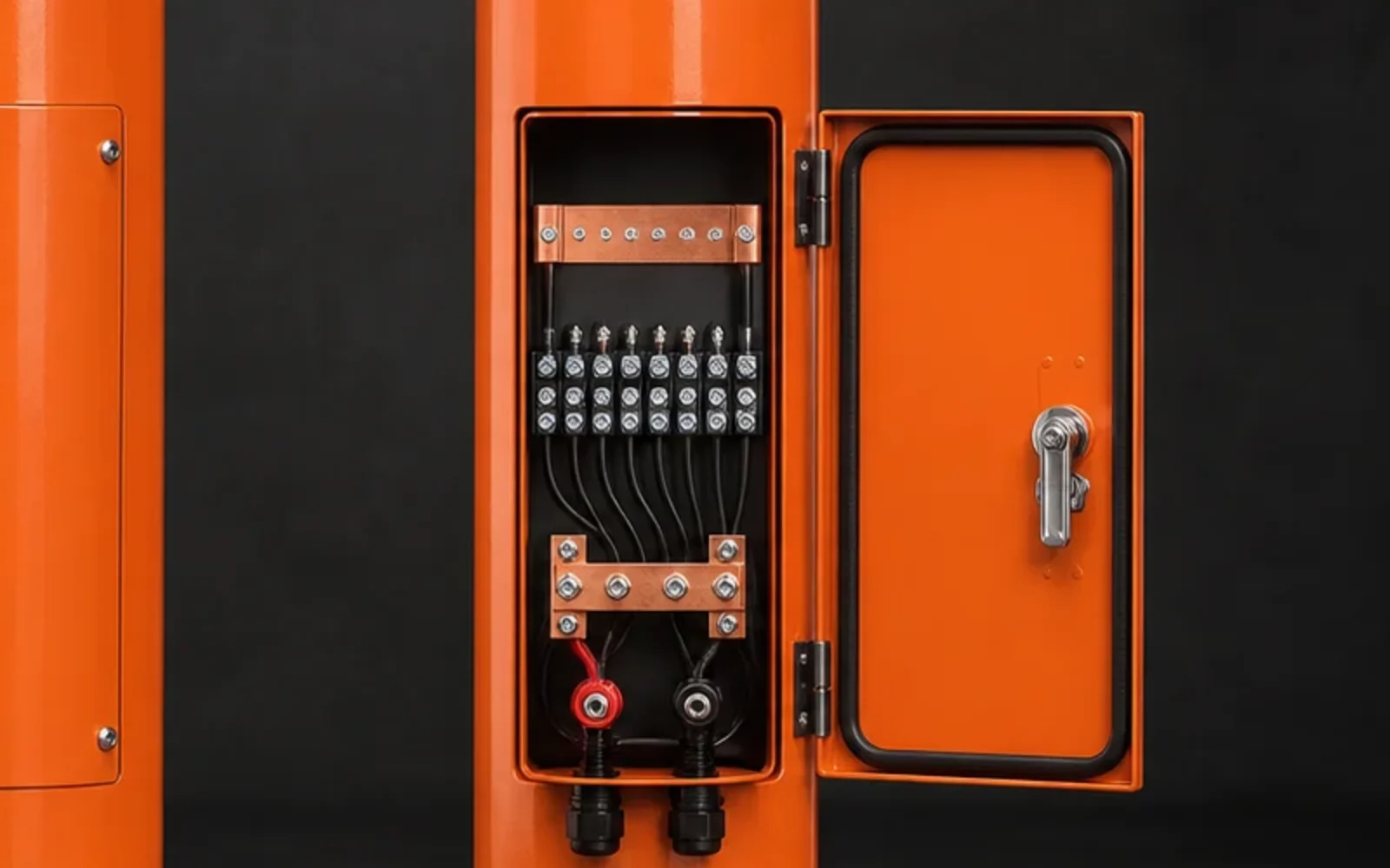
Links, terminals and glands readable at working scale
The point-to-point record and approved schematic remain the final basis for terminal function and circuit identity.
Product families
Configurations covered by this product range
Each configuration is released against its own datasheet, drawing or component schedule. Similar appearance does not make the technical definitions interchangeable.
Above-ground steel post
Robust lockable or bolted-access station for pipeline routes, with coating and foundation interface by drawing.
Nonmetallic test post
PVC/GRP configuration for projects that specify corrosion-resistant nonconductive construction.
Wall or pedestal enclosure
Compact box arrangement for plants, tank farms and sites with existing supports.
Monitoring-ready station
Internal space and interfaces prepared for a defined logger or remote monitoring unit without inventing unapproved electronics.
Applicable standards
Standards mapped to the part they actually control
Listing a standard is not a certification claim. The purchase specification must identify the required edition, clauses, tests and evidence. Project documents take precedence where they add or modify requirements.
| Standard and role | Scope | How it applies to this product |
|---|---|---|
| ISO 15589-1:2026CP system standard | Cathodic protection of on-land pipeline transportation systems, covering design, materials, equipment, installation and inspection. | The system designer's requirements for anodes, monitoring points, cabling, equipment and commissioning. It is not a standalone manufacturing certificate for every component. |
| NACE SP0169-2024Corrosion-control practice | Control of external corrosion on underground or submerged metallic piping systems. | CP criteria, design and installation context. Product configuration still follows the purchase specification and approved drawings. |
| NACE TM0497-2022Measurement method | Field measurement techniques related to CP criteria on underground or submerged metallic piping. | Measurement arrangement, reference-electrode use and cautionary measures. It does not define a universal reference-electrode product construction. |
| IEC 60529:1989+A1:1999+A2:2013Enclosure classification | IP Code classification for protection provided by electrical enclosures. | A required IP rating must be stated and supported by the selected enclosure or agreed assembly verification; it cannot be inferred from appearance. |
| IEC 62262:2002+A1:2021Mechanical-impact classification | IK Code classification for protection of electrical enclosures against external mechanical impacts. | Apply only when an IK rating is specified and supported by the enclosure design or evidence included in the order scope. |
| IEC 61666:2010+A1:2021Terminal identification | General principles for identification of terminals within industrial systems and equipment. | Terminal designations and schedules where the project adopts this identification approach. |
Edition review completed 22 July 2026. The edition named in the project requisition or purchase order remains the contractual basis.
Technical Data Sheet
Parameters buyers and engineers can verify
Numeric values are shown only where a current CathPro datasheet or recognized reference supports them. Custom assemblies use explicit project-defined fields instead of invented catalogue values.
Mechanical and environmental datasheet
These values define whether the station can be installed and maintained at the intended location.
| Parameter | Data to state | Verification basis |
|---|---|---|
| Station type | Post, pedestal, wall box or flush installation | Approved GA |
| Material | Carbon steel, stainless grade, GRP/PVC or project material | Material record/BOM |
| Dimensions | Overall height/width/depth, wall thickness and usable internal space | Dimensional inspection |
| Finish | Surface preparation, coating system, color and thickness if applicable | Coating procedure/report when specified |
| Access | Door/cover, hinge, lock/fasteners and opening clearance | Functional and visual check |
| Environmental rating | Required IP, IK or NEMA Type and evidence scope | Specified enclosure evidence or agreed test |
| Mounting | Base plate, embedment, wall brackets, pedestal or foundation interface | GA and fit-up check |
Terminal and circuit schedule
The rows below are typical functions, not a fixed wiring design. The project schematic determines actual quantity and connections.
| Circuit function | Datasheet fields | Factory check |
|---|---|---|
| Structure/pipe | Terminal ID, conductor size, color, links and destination | Label, termination and continuity |
| Reference electrode | Electrode ID, polarity, lead and dedicated terminal | Label and point-to-point continuity |
| Coupon | Coupon area/type, terminal, link and measurement arrangement | Component and schematic verification |
| Anode | Anode/group identity, cable size, link or shunt | Terminal/link rating and continuity |
| Bond/casing | Circuit identity, removable link, shunt/resistor/diode data | Component value and connection check |
| Spare/monitoring | Reserved terminal or device interface | Physical provision and label |
Internal component schedule
Every installed component should be identifiable on the drawing and bill of materials.
| Component | Controlled fields | Documented result |
|---|---|---|
| Terminal | Type, current rating, stud/thread, conductor range, color | BOM and count |
| Link | Material, section, hole spacing and removable arrangement | BOM and dimensional check |
| Shunt | Rated current, millivolt drop, resistance and tolerance | Nameplate/certificate when required |
| Resistor/diode/decoupler | Type, electrical rating, polarity and mounting | Manufacturer data and wiring check |
| Gland | Material, thread, cable OD range and environmental rating | Gland schedule |
| Nameplate/labels | Material, text, terminal designation and durability | Approved artwork/schedule |
Technical files
Published product datasheets
Cathodic protection test station datasheetCurrent summary of test-station types, materials and configuration support.Supply and assembly control
From approved data to an inspectable product
Project-sourced enclosures and components are configured and assembled by CathPro against released drawings, controlled interfaces and inspection records. No unapproved change is treated as equivalent by default.
Drawing release
Approve the GA, terminal schedule, schematic, BOM, gland schedule, labels and inspection plan as one document set.
Enclosure sourcing and preparation
Source the approved enclosure or prepare its access features and specified finish against the released drawing.
Panel preparation
Lay out the terminal board and component mounting so cable bend radius, tool access and clear identification are maintained.
Component assembly
Install terminals, links, shunts, glands and internal conductors exactly to the released BOM and schematic.
Identification
Apply station tag, internal terminal labels, polarity and circuit schedule after checking against the drawing revision.
Release verification
Perform dimensional, component, continuity, link/shunt and functional checks defined in the FAT/ITP.
Protected packing
Secure access panels, loose accessories and keys, and protect the finish and glands for transport and site storage.
Inspection and test plan
Checks tied to a stated acceptance basis
Inspection is useful only when the method, acceptance document and product identity are recorded together.
| Inspection item | Method or record | Acceptance basis |
|---|---|---|
| Enclosure and dimensions | Material/BOM, dimensions, access and mounting features | Approved GA |
| Components | Terminal/link/shunt/gland type, quantity and ratings | Approved BOM and component datasheets |
| Point-to-point verification | Continuity and circuit mapping for every terminal | Approved terminal schedule/schematic |
| Identification | External tag and internal terminal labels | Approved marking schedule |
| Finish and protection | Coating appearance/thickness when specified and enclosure evidence | Project coating and IP/IK/NEMA requirements |
Application range
Where this product family is used
- Cross-country pipelines
- Water transmission systems
- Tank farms
- Plant piping
- Insulating-joint monitoring
- Coupon and reference points
- Bond/interference locations
- Remote monitoring interfaces
Engineering selection notes
Points that should remain visible in technical review
- Do not select enclosure size before the terminal count, component layout, cable OD and bend space are known.
- An IP or NEMA label is not assumed from a stainless or painted enclosure; evidence scope must be defined.
- Hazardous-area equipment requires explicit classification, certified components and a project-approved design; it is not implied by a standard test station.
Documentation
Evidence that follows the supplied item
The final document set is defined by the order and ITP. Availability depends on the product, inspection scope and approved vendor-data requirements.
General arrangement drawing
Overall dimensions, material, finish, access, mounting and cable entries.
Terminal schedule and schematic
Terminal IDs, cable functions, links, shunts, devices and spare positions.
Bill of materials
Traceable component references, ratings and quantities.
FAT/inspection record
Dimensions, component verification, continuity, labels and functional checks.
Installation information
Foundation/mounting, cable-entry and terminal details needed by the site team.
Technical questions
Common specification points
Answers focus on product definition and evidence, not on sales instructions.
What is the minimum drawing set for a custom test station?
A general arrangement, terminal schedule or wiring schematic, BOM/component ratings, cable/gland schedule, marking schedule and inspection requirements should be controlled together.
How is the terminal layout verified?
Each terminal is checked against the schedule for identity, component type, connection and continuity. Links, shunts and polarity-sensitive devices receive additional value or orientation checks.
Does a metal enclosure automatically have an IP rating?
No. IEC 60529 classifies tested enclosure protection. The required rating and supporting enclosure/assembly evidence must be stated in the project scope.
What makes a station monitoring-ready?
The exact device, dimensions, power, antenna, communication, cable and environmental interfaces must be defined. Empty space alone is not a complete monitoring-ready design.