Engineering guide
High-Potential vs Standard Magnesium Anodes
Magnesium anodes come in two alloy families: magnesium–aluminum–zinc (standard potential) and magnesium–manganese (high potential). Their practical capacity is the same; the high-potential alloy works at a more negative potential, which matters in higher-resistivity soil. Values below are quoted from ISO 15589-1:2015 and EN 12496:2013.
Composition
Two alloy families, one key difference: manganese
ISO 15589-1 and EN 12496 both describe two generic magnesium anode alloys.
Alloy M 1 is a magnesium–aluminum–zinc alloy and is normally supplied in accordance with ASTM B843 (ISO 15589-1:2015, Table 7, footnote a). Alloy M 2 is a magnesium–manganese alloy with very low aluminum and zinc. In ASTM B843 orders the two families usually appear as grade AZ63B (standard potential) and grade M1C (high potential).
| Element, mass % | Alloy M 1 (standard potential) | Alloy M 2 (high potential) |
|---|---|---|
| Mn | 0.25 min | 0.5 to 1.5 |
| Al | 5 to 7 | 0.05 max |
| Zn | 2 to 4 | 0.03 max |
| Fe | 0.005 max | 0.03 max |
| Cu | 0.08 max | 0.02 max |
| Si | 0.3 max | 0.05 max |
| Pb | 0.03 max | 0.01 max |
| Ni | 0.003 max | 0.002 max |
| Others, total | 0.30 max | 0.30 max |
| Mg | remainder | remainder |
Source: ISO 15589-1:2015, Table 7. EN 12496:2013 Table B.3 lists the same two groups but gives Mn 0.15 to 0.7 % for alloy M 1 and limits other elements of alloy M 2 to 0.05 % each, so state which standard and edition the order follows.
Manganese is added to sequester iron impurities and to make the anode potential more negative. In both alloys the residual impurities have to be controlled to limit polarisation and self-corrosion (EN 12496:2013, B.2.1).
Performance
Potential, capacity and consumption
| Parameter | Alloy M 1 | Alloy M 2 |
|---|---|---|
| Open-circuit potential in soil, V vs CSE | -1.57 to -1.60 | -1.77 to -1.82 |
| Closed-circuit potential in soil, V vs CSE | -1.52 to -1.57 | -1.64 to -1.69 |
| Practical capacity in soil, Ah/kg | 1,100 | 1,100 |
| Practical consumption in soil, kg/A·y | 7.5 | 7.5 |
| Closed-circuit potential in seawater, V vs Ag/AgCl/seawater | -1.50 | -1.70 |
| Practical capacity in seawater, Ah/kg | 1,200 | 1,200 |
Sources: soil values ISO 15589-1:2015, Table 8 (saturated Cu/CuSO4); seawater values EN 12496:2013, Table B.4 (5 °C to 25 °C).
The practical capacities already include magnesium’s high self-corrosion, approximately 50 % (EN 12496:2013, Table B.4 Note). Capacity can be considerably lower at low current densities or over long operating periods (EN 12496:2013, B.2.2); ISO 15589-1 notes that current efficiency is reduced when the anode current density is below 200 mA/m², shown for alloy M 1 in its Figure 1 (ISO 15589-1:2015, 10.4 Note).
Selection
Why the high-potential alloy is used in higher-resistivity soil
A galvanic anode’s current output equals its driving voltage divided by the circuit resistance (ISO 15589-1:2015, 10.5, Formula 10). The driving voltage is the difference between the anode’s closed-circuit potential and the protection potential, which for carbon steel in most soils is -0.85 V vs CSE (ISO 15589-1:2015, Table 1).
With a closed-circuit potential of -1.64 to -1.69 V against -1.52 to -1.57 V for alloy M 1, alloy M 2 has the larger driving voltage and pushes more current through the same resistance. That is why the high-potential alloy is chosen where soil resistivity is higher. ISO 15589-1 still advises against magnesium anodes above 100 Ω·m (10,000 Ω·cm), even with backfill, unless an engineering evaluation or field test confirms the design (ISO 15589-1:2015, 10.4).
Because both alloys have the same practical capacity, a high-potential anode that delivers more current is also consumed faster for the same mass. Where the soil resistivity is low and the extra current is not needed, the CP design may select the standard-potential alloy instead.
Do not overshoot. For coated pipelines, ISO 15589-1 sets a limiting critical potential that should not be more negative than -1.20 V vs CSE, to prevent coating disbondment or blistering (ISO 15589-1:2015, Table 1 and text below it). Anode selection and spacing have to keep the structure within that limit.
Ordering
What to state in a magnesium anode RFQ
- Alloy and standard edition — for example an ASTM B843 grade, or alloy M 1 / M 2 of ISO 15589-1 or EN 12496. ASTM B843 is a prescriptive specification, not a performance specification (ASTM B843-18(2025), 3.1).
- Electrochemical evidence by batch — magnesium anode properties cannot be predicted accurately from composition alone, so documented short-term potential and capacity determinations should be considered for each batch or series of batches (EN 12496:2013, B.2.2). ASTM G97 is the laboratory test method for magnesium anode specimens for underground applications.
- The reference electrode for every potential — ISO 15589-1 soil values are against CSE, EN 12496 seawater values against Ag/AgCl/seawater; ISO 15589-1 relates CSE to the hydrogen scale as ECu = EH - 0.32 V (ISO 15589-1:2015, Table 1 Note 1).
- Marking and documents — anodes should be marked with the material type, anode mass without backfill and cast number; documentation of number, types, mass, dimensions, chemical analysis and performance data shall be provided (ISO 15589-1:2015, 10.2).
- Backfill package — buried magnesium anodes should be installed in backfill (ISO 15589-1:2015, 10.4); see the backfill and installation guide.
Questions
Short answers
- What is the difference between high-potential and standard magnesium anodes?
- Composition and potential. In ISO 15589-1:2015, alloy M 2 (magnesium-manganese) has a closed-circuit potential of -1.64 to -1.69 V vs CSE in soil, and alloy M 1 (magnesium-aluminum-zinc) -1.52 to -1.57 V. Both have a practical capacity of 1,100 Ah/kg in soil.
- Do high-potential magnesium anodes last longer?
- Not because of their capacity, which is the same for both alloys in ISO 15589-1. A high-potential anode delivers more current through the same resistance, so for the same mass it is consumed faster; anode life comes from the CP design.
- Which reference electrode do magnesium anode potentials use?
- ISO 15589-1 gives soil values against a saturated Cu/CuSO4 electrode (CSE); EN 12496 gives seawater values against Ag/AgCl/seawater. A potential quoted without its reference electrode cannot be checked.
Sources
Standards used in this guide
- ISO 15589-1:2015 Cathodic protection of pipeline systems — Part 1: On-land pipelines. Clauses 10.2, 10.4 and 10.5 (Formula 10); Table 1 and Note 1; Tables 7 and 8; Figure 1.
- EN 12496:2013 Galvanic anodes for cathodic protection in seawater and saline mud. B.2.1, B.2.2; Tables B.3 and B.4.
- ASTM B843-18(2025) Standard Specification for Magnesium Alloy Anodes for Cathodic Protection, Section 3.1. No ASTM B843 composition values are quoted in this guide.
- ASTM G97 Standard Test Method for Laboratory Evaluation of Magnesium Sacrificial Anode Test Specimens for Underground Applications (named as the test method; no values quoted).
Values are quoted from the editions listed. Where a project specification, purchase order or CP design states other values, those govern.
Factory supply & quotation
CathPro ASTM B843 M1C & AZ63B Magnesium Anode Supply
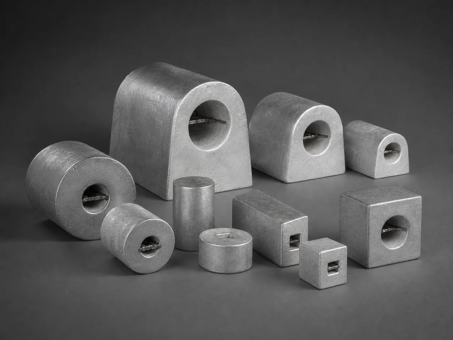
CathPro casts both high-potential M1C (−1.70 to −1.75 V vs SCE) and standard-potential AZ63B / H-1 (−1.50 to −1.55 V vs SCE) magnesium anodes across 37 standard D-shape, square and cylindrical sizes (1.36 kg to 45.4 kg), available bare or prepackaged with 75/20/5 backfill and custom CP lead cables.
Direct engineering desk (no web form required): sales@cathprocp.com · WhatsApp +86 159 7878 1890